A lathe is a machine with a rotating workpiece about an axis of rotation for various operations (turning, undercutting, knurling, drilling, facing, boring, and cutting) with lathe cutting tools applied to the workpiece to create an object with symmetry about that axis.
The tool used is a single-point cutting tool for general-purpose work, but the lathe (mult-point) cutting tools may be used for special operations. In the video below, you will be better able to visualize lathe machine operation.
In lathe machine work, different operations will require different types of lathe cutting tools based on the process of using of the lathe cutting tools.
Now let’s detail the various types of lathe cutting tools.
Types of Lathe Cutting Tools
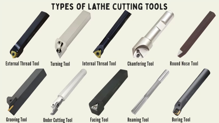
The following are the types of lathe cutting tools that can be used on lathe machine:
- Turning tool.
- Chamfering tool.
- Thread cutting tool.
- Internal thread cutting tool.
- Facing tool.
- Grooving tool.
- Forming tool.
- Boring tool.
- Parting-off tool.
- Counterboring tool
- Undercutting tool
- According to the method of applying feed
- Right-hand tool
- Left-hand tool
- Round Nose
Lathe Cutting Tools based on the Material Used
Various materials can be used to manufacture lathe systems. Each material has its own characteristics. Therefore, each lathe-cutting tool will have features determined by the mechanical properties of the materials used. Below are general lathe cutting tools (based on the material used to manufacture).
#1. High-Speed Steel (HSS).
High-speed steel is made from tungsten, carbon, vanadium, and chromium. These materials form cutting tools that are extremely strong, wear- and heat-resistant, and extremely hard. They exhibit a high speed that is suitable for rough and semi-finish machining.
#2. Diamond.
Diamond-based lathe-cutting tools are very hard to use on the machine. They are suitable for use on all materials. However, the material cost is very high. Carbide is similar in price, so being expensive limits its use in industry.
#3. Carbide.
Carbide cutting tools are considered hard, but brittle. Therefore, they are used on almost all materials. The high costs have limited its use for part production.
#4. Cubic Boron Nitride.
The other hard material is cubic boron nitride. These tools are very hard, wear-resistant, and suitable workpiece cast iron experiencing intermittent and rough machining.
Lathe Cutting Tools by Operation
Lathe cutting tools can be divided into categories as per the machining operation. Standard tools used in each operation is listed below.
#1. Turning Tool.
There are mainly 2 classes of turning tools:
- Rough turning tool.
- Finish turning tool.
Rough Turning Tool
The basic purpose of a rough turning tool is to remove as much metal as it can in a short a time as it will allow. The cutting angle is ground, so as to withstand maximum cutting pressure.
Finish Turning Tool
The turning tool is used to remove a minimal amount of metal. The tool angle is ground, so as to obtain a very smooth and accurate surface.
#2. Chamfering Tool.
Straight turning tools are also used as a chamfering tool, when the cutting edges are set at the angle of the chamfer.
Where a large number of chamfer work is to be done, a special chamfering tool can be made, having the side cutting edge angle ground to the angle of the chamfer.
#3. Shoulder Turning Tool.
A square shoulder can be turned by a knife-edge turning tool, or facing tool. A bevelled shoulder may be turned by a straight turning tool, having a side cutting edge angle and zero nose radius.
A filleted should can be turned by a straight turning tool, having a nose radius to fit match the radius of the fillet of the workpiece.
#4. Thread Cutting Tool.
External Thread Cutting Tool
American “V” threads are produced by a single-point thread cutting tool. The edges are sharpened to the shape and size of the thread to be cut.
The shape of the tool is determined by the included angle at the nose of the tool, which should correspond to the angle of the thread. This angle may be 60° for metric threads or 55° for B.S.W threads.
The size or cross-section of the cutting edges also depend upon pitch of the thread. The contains an H.S.S. thread-cutting tool shown below.
So for machining different screw threads with different pitches separate tools are used to produce accurate threads. The nose of tool is pointed, flat, or rounded according to the shape of the root of the thread.
After grinding the tool, a thread tool gauge is used to check the shape and size of the tool.
Tool for cutting square threads
The side clearance of tool for cutting square thread has the utmost importance to prevent interference or to not rub against the vertical flank of the thread.

As a rule, forward clearance angle is determined by adding 5° to the helix angle of the thread and trailing side clearance is found by subtracting 5° from the helix angle, if ø is the forward side clearance angle and θ is the trailing side clearance angle, then from the formula:
The width of the cutting edge should be half the pitch of the thread.
Small clearance angle of 1° to 2° are provided at the side of the tool to prevent the surface from ribbing with the work.
Internal Thread Cutting Tool
The cutting edge of the tool is exactly the same as an external thread cutting tool, except the front clearance angle in increased sufficiently as in a boring tool.
This tool is of the forged type orbit type and is secured on a boring bar. The point of the tool must be set square with the work.
#5. Facing Tool.
A facing tool cuts metal using its side cutting edges; no top rake is needed. The figure shows an H.S.S. facing tool, for finishing.
It has a 2° side cutting edge angle and a 34° end cutting edge angle to fit in the space, or to be able to leave a 2° for clearance on either side, between the end work and 60° dead center.
The shank sections are standard at 20Χ20, 25Χ25, 32Χ32, 40Χ40, and 50Χ55 – stated in mm. The tool length is standard at 125, 140, 170, 200, and 240 mm too. The nose radius is standard at 0.5 to 1.6 mm.
#6. Grooving Tool.
The grooving tool shares similarities to the parting off tool in the figure. The edges of the cutting edges are square, rounded, or have a “V” shape – depending on the shape of the groove to be cut.
#7. Forming Tool.
Turning curved profiles may be affected by using
- Ordinary lathe tools,
- Flat forming tools,
- Circular forming tools.
An ordinary lathe turning tool is an efficient and effective method, particularly when pairing the tool with a copying attachment that reproduces the form accurately. Flat-forming tools take two shapes:
- Simple forming tools
- Flat dovetail forming tools.
#1. Basic forming tools.
These tools are ground to the specific shape of the groove, undercut, or thread to be made.
Flat dovetail-forming tools are ground to a wider cutting edge to match the depth of the desired shape. The tail end of the tool is attached to a specific tool holder and typically has no front rake but does have a sufficient front clearance angle from 10° to 15°.
Regrinding is done always only on the top face of the tool and will not change the form of the tool.
#2. Circular Form Tools.
This type of tool form is used most often in production work because it will have a long cutting surface which will yield a longer tool life.
The centre of the tool is set slightly above the centre line of the work to provide an effective front clearance angle on the tool. If the centers are the same height, the tool will rub against the work.
The tool centerline is usually about 1/20 to 1/10 of the tool diameter higher than the lathe centerline, which is termed ‘offset’. Regrinding is done by only grinding the flat.
#8. Boring Tool.
A boring tool is essentially a left-hand external turning tool in terms of its cutting edge.
The tool can be either a bit type inserted into a boring bar or holder, or a forged type which has a tool shank.
The figure shows an H.S.S. tool bit inserted into a boring bar.
A boring bar is mild steel and the tool bit is frictionally held in the bar with slotted and/or hole cut into the boring bar and locked into position a upright Allen screw. The amount of tool projection of cutting edge from the center of the boring bar determines the finished hole size of the work.
Generally, the bit is inserted at ninety degrees to the center line of the bar for boring a continuous hole passing from one end of the bar to the other end of the boring bar.
Different Designs of The Boring Tool
The tool bit is set at a single to the axis and projecting beyond the end of the bar depending the type if a blind hole is to be bored.
- For rapid machining, a tool bit having two cutting edges at its two ends can also be called a boring tool bit is used.
- To finish the boring operation, a wide double-bladed cutter bit can be inserted in the boring bar.
- For boring with different diameters, two or more bits can be inserted in a boring bar in two positions in both directions in one machine set-up.
The Boring Bars
- The boring bar for boring smaller holes in the range of 12 to 100 mm diameter are held in the tailstock body.
- For boring larger diameter holes, the boring bar can also be gripped by two clamp block or projected holding device and held in the tool post body.
- For boring larger hole diameters in order to have the precision boring or boring in size work that is support on cross-slide use the same bit that is supported on centers and made to revolve.
Clearance for Boring Tool
- In a boring tool, the tool’s cutting edge must have sufficient front clearance to clear the work when it is being inserted into the work when the tool is in the boring position.
- In order to strengthen the tools, point of double clearance (primary and secondary) must be provided.
- As the diameter of the hole being bored increases, the front clearance must also increase in size.
- The larger clearance angle requires the rake angle in a boring tool must be reduced.
- The nose of the tool can be in a straight or round cutting shape according to type of finish required and diameter of hole being bored.
#9 Counterboring Tool
A boring tool can carry out the counterboring operation. The tool cutting edge is ground such that it produces a shoulder after turning. The counterbore has multiple cutting edges.
#10 Undercutting Tool
The undercutting or grooving tool has a point and the form of the cutting edge have the same form as the required groove.
Clearance angle is given along all the sides of the tool. For the undercutting or the grooving of the cutting edge, the longitudinal feed is used. The front clearance angle is dependent on the bore of the work.
#11 Parting-off Tool
A parting-off tool is usually forged and used as bits for cemented-carbide tipped tools. A parting-off tool is made as narrow as possible to take off the minimal amount of metal.
The width range is between 3 to 12 mm for the cutting edge. The cutoff length for the tool to insert into the work should be slightly longer than the radius of the bar stock being machined.
As the tool cuts deep into the work, clearance is provided all around the tool cutting edge to prevent it from rubbing against the work surface.
As the tool has a purely ended cutting it has no side rake but slight back rake is offered on the tool to aid an easy break of the chips.
Lathe Cutting Tools Based on Applying Feed
- Right-hand tool
- Left-hand tool
- Round Nose
#1. Right-Hand Tool.
The tool shown in the figure is a right-hand tool. It is one that is fed from the lathe bed, i.e., from the tailstock to the headstock end, when operations like turning, thread cutting, and the like are taken.
A right-hand tool is formed on its left-hand end when viewed from the top with its nose pointing away from the operator.
#2. Left-Hand Tool.
The left-hand tool shown in the figure is fed from the left to the right-hand end of the lathe bed, i.e., from the headstock to the tailstock end of the lathe.
The left-hand tool is performing left-hand thread cutting operations or turning operations which leave a shoulder on the right-hand end of the workpiece.
A left-hand tool has its cutting edge formed on its right-hand end when viewed from the top with its nose pointing away from the operator. A left-hand tool may also be used for facing.
#3. Round Nose Tool.
A round nose turning tool is also shown in the figure. It must be fed from the left to the right or from right to left when the tool is away from the lathe bed. For this reason, it has no back rake and also has no side rake.
In some instances, there is a small back rake provided on the tool. A round nose turning tool is usually used when finishing turning.
Lathe Cutting Tools Sorted by Structure
Lathe cutting tools are devised in three primary ways, based on the structures involved.
#1. Single Body Tools.
Single body cutting tools are constructed of any shape, size, geometry, and are made from one material. Single body lathe machine tools are the fastest and strongest tools and are compounded from optimal lathe tool.
#2. Welding Lathe Cutting Tools.
Welding tools have a rod and a head made of different materials, and welded together. The flank is made of strong, durable material, like carbide, and the body can be made from various metals.
Welding tools will exert less cutting force than single body – due to differences in rigidity, and thus, tooling performance.
#3. Clamp Lathe Cutting Tools.
The material structure of clamp lathe cutting tools is similar to welding tools. The difference being that a clamp lathe tool is formed by placing an insert (i.e. cutting tool) on a handle bar, unlike the welded tool.
Clamp lathe cutting tools are flexible and interchangeable, and in practice, insert determines tooling characteristics, such as strength or durability.